Here I present a headphone amplifier with active noise cancellation. I designed this a long time ago, so I probably wont be able to elaborate on the math and specs. What I do recall is the gain for the main stage being somewhere in the neighborhood of 26 dB. On the left hand side, we have a noise cancellation circuit that basically uses a condenser microphone whose geometry is designed to pick up ambient noises. These noises are amplified, inverted and super-imposed onto the audio input signal. A potentiometer will help vary the amount of noise cancellation. Another potentiometer is used to vary the tune (between emphasis on low frequencies or high frequencies). A loudspeaker equivalent circuit was used to introduce the impedance and resistance of the headphone into the circuit for analysis. A high-fidelity Sony studio headphones was considered. Zobel networks are used as required to stabilize the reactive elements of the circuit. Capacitors are used to eliminate DC offset and send a pure AC signal to the headphone.
 While choosing coupling capacitors, I did some research myself to find the sweet-spot between capacitor value and attenuation of low frequencies. Higher value capacitors don’t attenuate low frequencies. I choose 47 uF for input and 1000 uF for output coupling based on the following study.
TIME DOMAIN ANALYSIS:
FREQUENCY DOMAIN ANALYSIS:
OLD SCHEMATICS AND WORK:
SCROLL UP FOR NEW ONE.
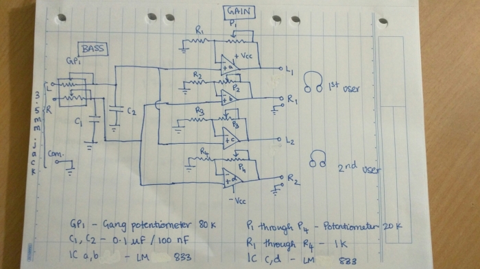
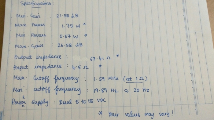
Ref. Data: Impedance of Sony MDR 7506 is 63 Ohm, output impedance of iPhone 5 is 4.5 Ohm, and LM833 at Av rounded to 10 is roughly 1 Ohm.
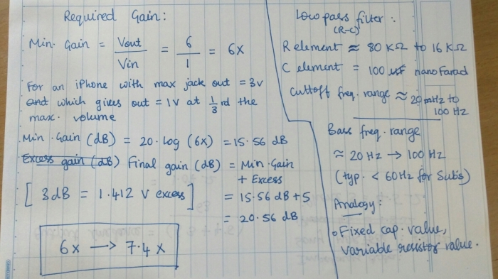
NOTE: R1 and R2 potentiometers help you control cutoff frequency of the L and R channels independently while the 300 k pots. help you adjust gain with a max. gain factor of 7.4x. Use a very low R1 and R2 resistance setting to increase the frequency range i.e., let you hear the high pitched instruments clearly. For a music track with low, bassy instruments, I’d stick to a higher setting to bring the cutoff frequency of the RC filter to somewhere around the neighborhood of 100-200 Hz. Remember, gain is directly proportional to the 300 k pot. setting while cutoff frequency is inversely proportional to R1 and R2 pots. setting.
The output impedance above should have been 1.07 Ohm, I made a math error by using the typical open loop output impedance which is 37 Ohm haha. This op amp has a high output voltage swing ,fast response time, and a 7 V/microsecond slew rate. Studying the characteristic graphs from the documentation, there is a 1 V/microsecond slew rate difference on the falling edge when a 18 V power supply is used. The output voltage Vo peaks at 15 when used with 18 V dual supply instead of 5 V. This is highly recommended since our build requires Vo in excess of 5 V and might help reduce clipping. The LM833 produces its full Vo upto 100 kHz. The distortion factor is 0.001% up to 20 kHz. Further, it has favorable noise and distortion characteristics, making it ideal. The sweet-spot for best phase and gain margin is when the output load capacitance is around 200 pF. You can observe these characteristics using an oscilloscope(if you have one!)


