Greetings people! Introducing the “Engineering Everyday” series where I explore and engineer our typical everyday problems which you and I may run into at home, work or play. I’m initiating and hoping to keep up this series. I however, will not establish a publishing schedule at this moment as my blogging trends are fairly irregular.
Alright, let’s jump straight in, I have been noticing my power amplifier makes this ‘pop’ sound every time I turn on a fluorescent light or fan which shared the same AC line. This amp is hooked up to the surround speakers and is part of the entertainment system. It didn’t take much thinking to figure out these noises were caused by EMI or voltage fluctuations in the line introduced by the ballasts and surge capacitors of the fore-mentioned appliances. This was clearly a case of conducted EMI.
Without further ado, I CAME TO THE RESCUE! *Star Wars theme* I was clearly the only engineer in town who could fix this! Not to mention my unprecedented record of projects in the past failing so perfectly, almost every time testifying how the law of infinite probability does not hold true for my work. One shocked me, not once but twice (Electrically, not emotionally). One even had the courtesy to annihilate itself from physical existence (or maybe I just lost it). Most of my creations are put to no good use and are retired to be stored indefinitely at grandparent’s place.
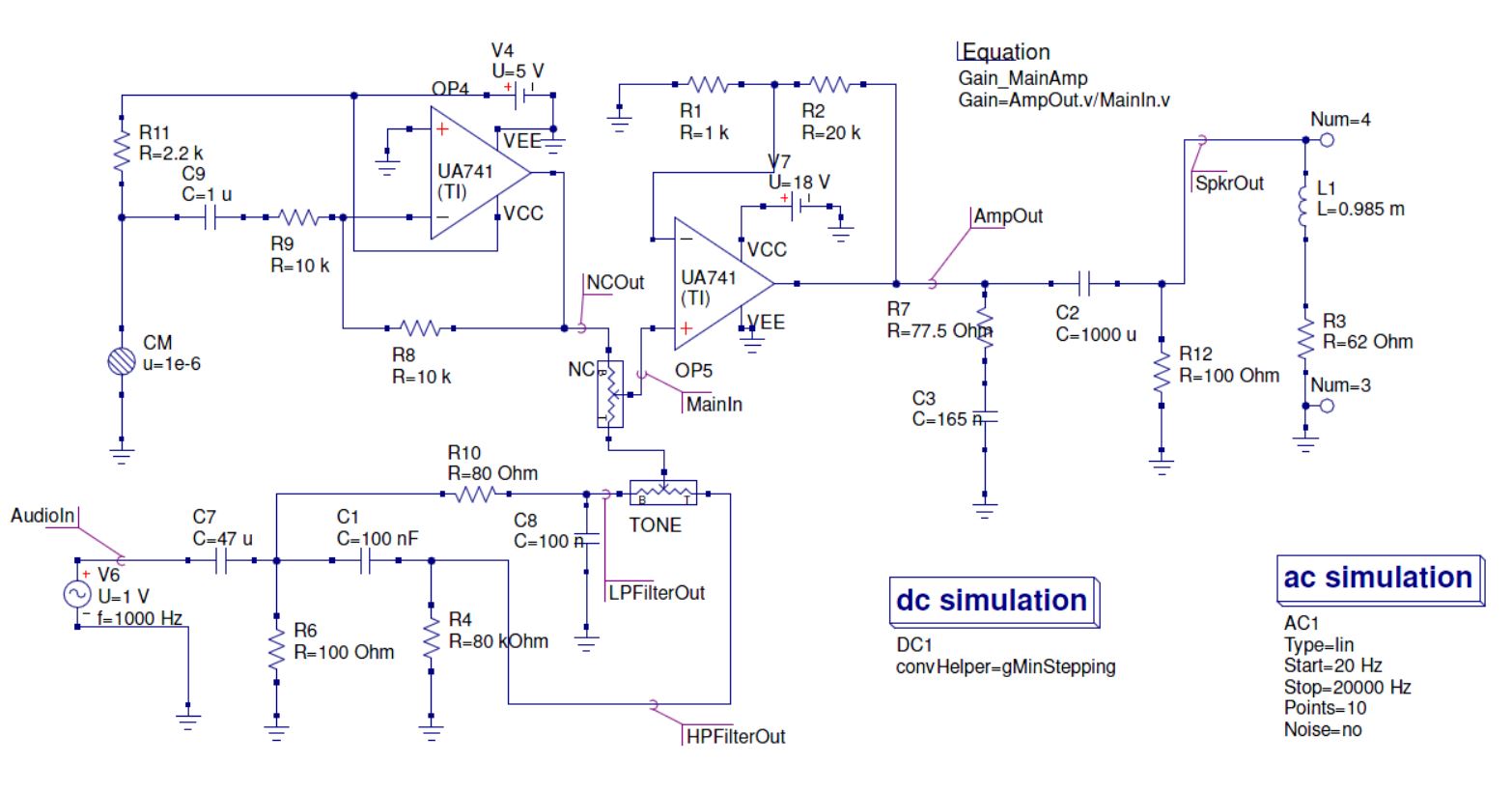
Here I present a headphone amplifier with active noise cancellation. I designed this a long time ago, so I probably wont be able to elaborate on the math and specs. What I do recall is the gain for the main stage being somewhere in the neighborhood of 26 dB. On the left hand side, we have a noise cancellation circuit that basically uses a condenser microphone whose geometry is designed to pick up ambient noises. These noises are amplified, inverted and super-imposed onto the audio input signal. A potentiometer will help vary the amount of noise cancellation. Another potentiometer is used to vary the tune (between emphasis on low frequencies or high frequencies). A loudspeaker equivalent circuit was used to introduce the impedance and resistance of the headphone into the circuit for analysis. A high-fidelity Sony studio headphones was considered. Zobel networks are used as required to stabilize the reactive elements of the circuit. Capacitors are used to eliminate DC offset and send a pure AC signal to the headphone.
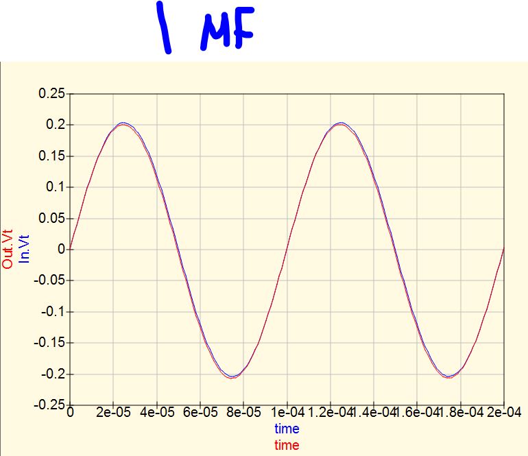
While choosing coupling capacitors, I did some research myself to find the sweet-spot between capacitor value and attenuation of low frequencies. Higher value capacitors don’t attenuate low frequencies. I choose 47 uF for input and 1000 uF for output coupling based on the following study.
TIME DOMAIN ANALYSIS:
FREQUENCY DOMAIN ANALYSIS:
OLD SCHEMATICS AND WORK:
SCROLL UP FOR NEW ONE.
Ref. Data: Impedance of Sony MDR 7506 is 63 Ohm, output impedance of iPhone 5 is 4.5 Ohm, and LM833 at Av rounded to 10 is roughly 1 Ohm.
NOTE: R1 and R2 potentiometers help you control cutoff frequency of the L and R channels independently while the 300 k pots. help you adjust gain with a max. gain factor of 7.4x. Use a very low R1 and R2 resistance setting to increase the frequency range i.e., let you hear the high pitched instruments clearly. For a music track with low, bassy instruments, I’d stick to a higher setting to bring the cutoff frequency of the RC filter to somewhere around the neighborhood of 100-200 Hz. Remember, gain is directly proportional to the 300 k pot. setting while cutoff frequency is inversely proportional to R1 and R2 pots. setting.
The output impedance above should have been 1.07 Ohm, I made a math error by using the typical open loop output impedance which is 37 Ohm haha. This op amp has a high output voltage swing ,fast response time, and a 7 V/microsecond slew rate. Studying the characteristic graphs from the documentation, there is a 1 V/microsecond slew rate difference on the falling edge when a 18 V power supply is used. The output voltage Vo peaks at 15 when used with 18 V dual supply instead of 5 V. This is highly recommended since our build requires Vo in excess of 5 V and might help reduce clipping. The LM833 produces its full Vo upto 100 kHz. The distortion factor is 0.001% up to 20 kHz. Further, it has favorable noise and distortion characteristics, making it ideal. The sweet-spot for best phase and gain margin is when the output load capacitance is around 200 pF. You can observe these characteristics using an oscilloscope(if you have one!)
I worked on this like a year ago, and probably the last DIY electronics project I did during recent times. I’m a music maniac and like anyone who loves enjoying music, I wanted a good music system (though I have one now). I had a couple of surround speakers lying around and thought I’d make good use of it if I could design a simple power amplifier. I was no good dealing with power transistors at that time, like MOSFETs so I decided on a chip amplifier. I couldn’t source components required for advanced builds so I stuck to a primitive(yet discontinued) chip from Sanyo. The LA4440 requires very little external components, a couple of electrolytic capacitors like any audio system.